Sometime lucker, first time poster.

This is my first post to the community, but I've been reading the board for a while. I learn a lot from veterans posters by doing simple search from the forum or other search engines. Thanks to those contribute and share ideas.
I have not found anyone posting information on how to modify the simple Door/Window sensor (DS10A) to be a "Normally Open" switch other than
Puck method of using the test button. The test button method work well with short momentary open/close contact but for prolong contact, it may not work because the longer the test button being push, the security code also change (if I read that right).
My other found that
save-on-security sell a modify DS10A to a normally open contact for 75 can bucks is bloody expensive for a simple mod. Well whether my method is the same or different from them is
I don't know.
OK here you go.
Part needed:
- (1) NPN General Purpose transistor. I use 2N3904
- (1) 100K-150K 1/8W resistor. I use 150K 1/4w.
- 1 or 2 inches of small heatsink tube (optional) and soldering tools....
The transistor and a resistor wouldn't cost you more than 50 cents but because you can't really buy it in single piece, so it may cost you about 2 bucks for couple resistors and a transistor. Radio shack should have them on their shelf.
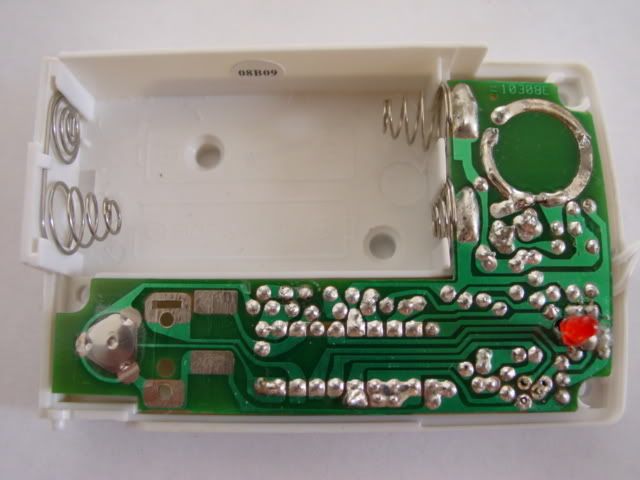
DISCLAIMER: First I'm not an EE guy. I just happen to understand a little how electronic works and by searching the net read the datasheet to come up with the modification. This modification will void your x10 warranty on the sensor. And if you are not comfortable with the soldering iron, don't do it. The result power consumption is suppose to be more than the original because of the added components. How much more, I don't know because my cheapo digital meter can't read the power consumption before and after the mod. So expect to change battery more often that you normally do. But I don't think it's that bad.- Remove the battery, unscrew 3 screw to take the case apart. Be carefully so you don't drop the "test" button and slider switch.
- Remove all hot glue around the 2 wires and resistor. Use some hard plastic or jewelry/glasses type screw driver to take them off.
- Desolder/Remove the wire closer to the 3 transistors. You can leave the one closer to the battery(or circle antenna) in there. But It's much easier to work with when no wire dangling around. So I remove both.
You end up with something like this.
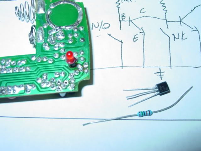
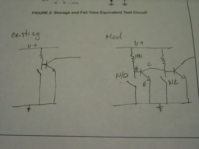
This is the sketch of existing and mod circuit.
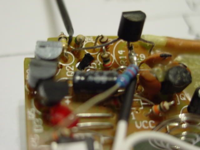
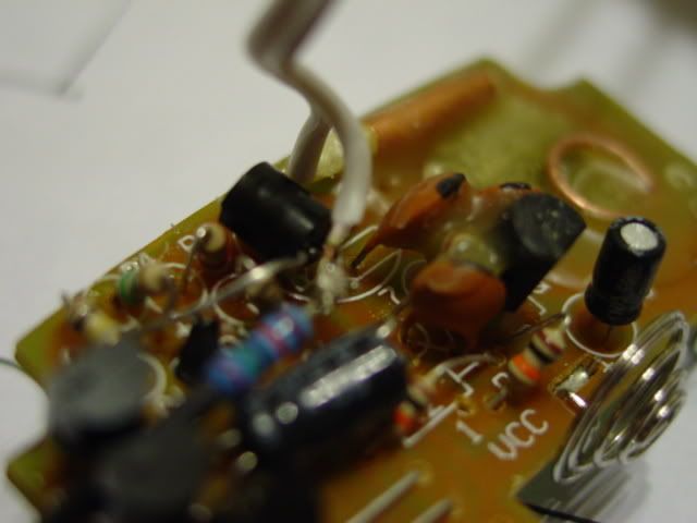
- Cut the middle pin of the transistor (base) and solder it to 1 end of the resistor and 1 of the wire that you de-solder earlier. If you look at the image, the
Collector pin is the one on top or left. This pin will be solder to the hole (between 2 resistors) that was from the wire you de-solder.
Emitter is the pin on the right or lower. It will be solder to ground point.
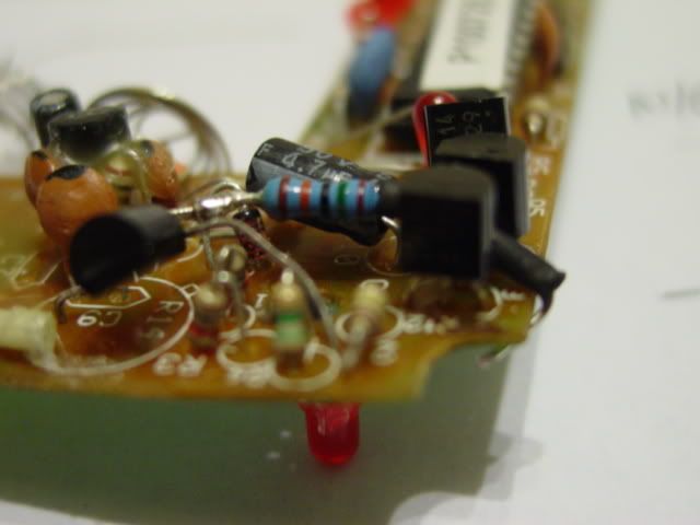
- Solder the transistor like the image below.
Collector pin go to the hole from remove of existing wire between 2 resistors. Next to the antenna area (C9 print), there is an unused hole that you can use for ground. Solder emitter pin to this hole.
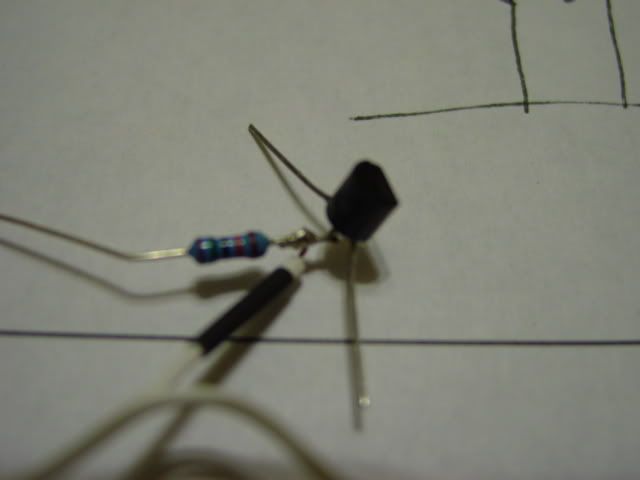
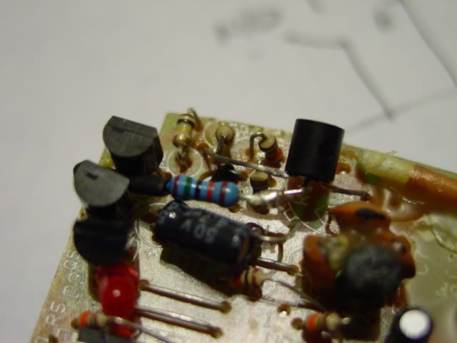
- Bend the transistor pins and the resistor pin so that they don't touch other component. Cut the resistor so that it can bend like the image below. This end of the resistor will be solder to
the right most pin of the existing transistor. If you have heat sink tube, you can use to help protect against short if they accidentally touch. I forgot to take picture of the under side of the board.
Couple more shot of how the added transistor/resistor is bent.
- Now if you remove the other wire like I did, time to put it back.
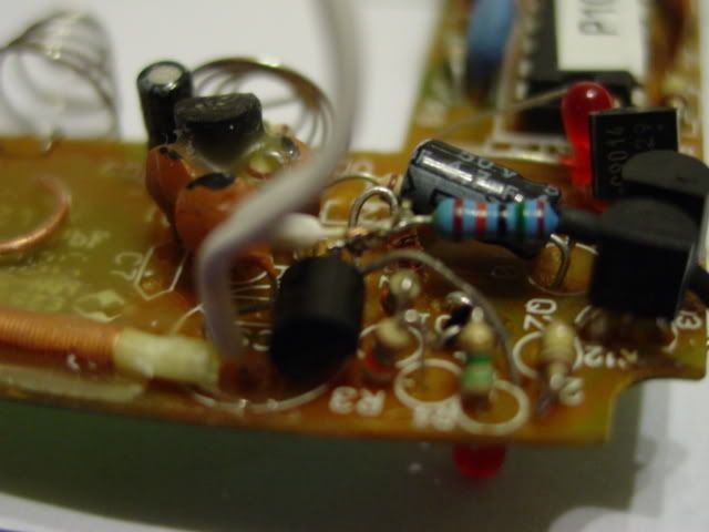
There you have it. A
normally open DS10A modification that cost you 50 cents and 15-30 minutes of your time.
My main reason to modify the DS10A is to be able to connect it to the smoke detector.
I know
James S already using the DS10A as smoke detector, but he use relay to do it. A mechanical relay is typically consume more juice. A SSR is a much better one, but most of SSR are normally open relay.
I also run into one of the thread by iceblue
Regarding to modify using photocell which mention of led pickup. That method is oddy complicated.
So I said, why not combine the 2 together. Most SSR are basically a optocoupler device. So I look into optocoupler, and I found a thread posted by Puck
Using optocoupler to extend the arm led on the security dialer. Opto coupler is basically led level voltage normally open switch. Instead of SSR, I can use optocoupler, much much cheaper than SSR.
Now I can link all smoke detectors together from the detector to the DS10A instead of running wire from 1 detector to another. The SA304 with escape light is 10 bucks at wally world.


 Author
Topic: MOD: Normally Open DS10A the cheap way. (Read 17861 times)
Author
Topic: MOD: Normally Open DS10A the cheap way. (Read 17861 times)